The service manual for the 1971 AMI/Rowe MM5 Presidential jukebox contains lots of useful information. I have trouble with the "Troubleshooting" pages. They are very nicely described, but I have problems identifying the parts they reference. You really do need the service manual, but this table was written to help me remember where the parts are and what I did.
| Problem |
Possible Cause |
Remedy |
| Credit and Selection System |
| Valid coins fail to pass through slug rejector into cash box. Coins remain jammed in rejector. |
Dirt or foreign matter clogging coin passages in rejector. |
Refer to coin rejector service manual for cleaning procedure. Clean in accordance with instructions. |
| Scavenger binding, rejector out of adjustment. |
Refer to coin rejector service manual for adjustment procedure. |
| Valid coins pass through rejector into coin box but credit is not established. |
Coin switch contacts dirty, bent, or broken. |
Adjust coin switches. Check for bent or broken contacts. Clean contacts. |
| Incorrect alignment of slug rejector or coin switches. Coins drop between switch levers. |
Be sure that slug rejector is firmly clamped in place. Adjust coin switches as necessary. |
| Credit coil plunger binding. |
Check credit coil plunger for binding due to dirt. Check coil windings for continuity. |
| Blown 0.6A fuse in credit unit. |
Check for binding coin switch. |
| Coin switch connector not seated. |
Check that connector is firmly seated. Check for broken wire in common line. |
| Valid coins are accepted but credit lamp does not light. |
Lamp burned out. |
Replace lamp. Check for broken wires. |
| Broken wiper blade on credit unit wiper arm assembly. |
Replace wiper blade. Check that credit unit edge connector is firmly seated. |
| Coins accepted; credits not registered properly-credit unit fuse blows. |
Coin hanging up on coin switch. Coin switch not opening. |
Check for jammed coin. Free binding coin switch. |
| Coin switch contacts closed by metallic foreign matter. |
Clean contacts and replace fuse. |
| Continuous free play. Credit light remains on. |
Credit coil plunger binding in raised position. |
Free credit coil plunger. Replace credit coil if necessary. |
| Cancel coil burned out. |
Check cancel coil for continuity. Check for burned appearance. Replace defective coil. |
| Cancel circuit open. |
Check credit cancel coil. |
| More than normal number of credits established for coin deposited. |
Appropriate stop coil not being energized. |
Check for intermittent open circuits, loose wires, or poor solder connections. |
| Appropriate stop coil plunger sticking. |
Manually actuate plunger to check for free operation. Clean or replace plunger or spring if necessary. |
| Improper credit set-up. |
Check pricing against credit and pricing chart. |


 is closest to the latch solenoid on the left, the select pulse latch relay (R1) is the one closest to the wiring loom on the right.")


|
| Valid coins accepted, credits are established, pushbuttons do not latch in. |
Latch coil not operating. Select pulse and latch relay R1 not picking up. |
Check coil for continuity. Check relay contacts for closure. Replace relay or coil if necessary. |
| Select pulse and latch relay R1 contacts broken, dirty, or out of adjustment. R1 not picking up after credit is established. |
Clean and adjust relay contacts. |
| Open circuit between credit unit and select pulse and latch relay RI. R1 not picking up after credit is established |
Check for open circuit. |
| Pushbuttons latch in, but release prematurely; no selection played. |
Select pulse and latch relay R1 time delay circuit giving short pulse. |
Check diode on selector assembly. Check relay R1 for dirt between core and armature. Replace parts if necessary. |
| Pushbuttons latch in; no further action. |
Open circuit to search unit motor. |
Check wiring. |
| Pushbuttons latch in, search unit motor starts, but runs continuously. |
Open circuit in selector assembly, wiring from pushbutton switches to search unit printed board segments. |
Check selector assembly wiring. |
| Contacts on mechanism control relay R dirty, broken, or out of adjustment. |
Check mechanism control relay R for proper operation. Replace if necessary. This relay is nonrepairable. |
| Selection is registered magazine rotates one complete scan cycle and stops. No record is played. |
No circuit through stop switch. |
Check wiring to stop switch. |
| Selected pin not pushed far enough; select coil not properly positioned. |
Check inside and outside row select coils for proper operation. Adjust select coil arm assembly. |
| Wrong selection is played every time. |
Search unit select coil arm assembly out of adjustment. |
Adjust search unit select coil assembly. Check search unit wiper adjustment. |
| Stop switch out of adjustment. |
Check stop switch alignment. |
| Stop switch gear not properly installed. |
Check stop switch gear alignment. |
| One particular letter or number, in combination with all letters and numbers, will not register. |
Open circuit in the particular letter or number wiring. |
Check for dirt on search unit commutator board or wiper contacts. Clean with alcohol, if necessary. To locate the open circuit, make 20 selections in the following order: A1, B1, C2, D2, E3, F3, G4, H4, J5, K5, L6, M6, N7, P7, Q8, R8, S9, T9, U0, V0. This test combination will determine which letter or number has an open circuit. |
| Search unit motor energized but does not run. |
Search unit gears binding. |
Check for dirt or foreign matter lodged in gear teeth. Check backlash adjustment. |
| Tip of select coil plunger hung up on side of pin, excessive backlash causing select coil arm overtravel. |
Adjust search unit gears for proper backlash. |
| Only one selection is made but two selections play. |
Select coil plunger hitting two adjacent pins; select coil arms out of adjustment, or overtravel caused by excessive gear backlash. |
Adjust select coil arm assembly. Adjust search unit gears for proper backlash. |
| 50¢ coin establishes only 25¢ credit (50¢ bonus relay being used). |
50¢ bonus relay not picking up, or picking up and dropping out prematurely. |
Replace 50¢ bonus relay. Check that relay is firmly seated in socket. |
| Record Changer Mechanism |
| All selections register properly but magazine does not rotate. |
Scan Assembly not operating. |
Check scan coil for open, check for binding linkage. |
| Scan switch defective or out of adjustment. |
Check scan switch for proper operation, adjust switch position. |
| Diode D-1 open. |
Check by shorting across diode. |
| Cam switch CS2 faulty or out of adjustment. |
Check switch for proper operation or adjust switch position. |
| Magazine detent coil open or binding detent linkage. |
Check coil for continuity, free linkage. |
| Relay contact 1 & 9 faulty. |
Check relay, replace if necessary. |
| Detent switch faulty or out of adjustment. |
Check switch for proper operation or adjust switch position. |
| Magazine motor faulty or drive gears binding. |
Check motor and gear train for proper operation. |
| Scan linkage operates, magazine one complete scan cycle and stops - no record is played. Stop switch jumps pins. |
No circuit through step switch. |
Check stop switch and wipers on back of stop switch. |
| Diode D-2 defective. |
Check diode. |
| Short circuit in 50 MFD capacitor. |
Check capacitor resistance. |
| Faulty mech. relay. (R) |
Replace relay. |
| CS5 cam switch defective or out of adjustment. |
Check cam switch for proper operation - replace if necessary, adjust switch position. |
| Short circuit on common side of magazine detent coil. |
Check detent coil circuit. |
| Magazine stops at proper selection, but record transfer assembly does not operate. Relay (R) picked up. |
Open circuit to transfer motor. |
Check relay contacts 6 and 10, 7 and 11, for proper operation. |
| Defective transfer motor. |
Check motor, replace if necessary. |
| Transfer arm stops in mid travel between magazine and turntable. Phono power is on. |
Cam switch CS2 faulty or out of adjustment. |
Check for proper operation of switch. Replace if necessary. Adjust as required. |
| Blown fuse in junction box. |
Check 2—8/10 (2.8) and 6-1/4 (6.25) Amp fuse in junction box. Replace if necessary. |
| Transfer arm moves each selection record from magazine to turntable and back without being played, all other functions normal. |
Diode D-3 shorted. |
Check for short. |
| Short circuit in cancel line, cut off switch or automatic cancel circuit. |
Check for short. |
| Cam switches CS4 or CS5 faulty or out of adjustment. |
Check switches - adjust or replace if necessary. |
| Needle height improperly adjusted. |
Adjust height of needle. |
| Wrong side of record plays; selection is improperly registered. |
Center slip ring wiper broken or out of adjustment. |
Adjust or replace. |
| Left side switch in stop switch assembly faulty. |
Check left side switch - replace if necessary. |
| Toggle switch coil open or linkage binding. |
Check coil and linkage. Replace or free if necessary. |
| Diode D-3 open. |
Check diode. |
| Cam switch CS4 faulty or out of adjustment. |
Check switch, replace or adjust if necessary. |
| Mechanism relay (R) contacts 5 and 9, not making connection. |
Check relay — replace if necessary. |
| Wrong record played, selection is properly registered. |
Stop switch gear out of adjustment. |
Align 200 mark on stop switch gear with step in search unit mounting bracket.

|
| Stop switch out of adjustment. |
Align stop switch. |
| Selections play over and over, pins not being reset. |
Slip ring wipers No. 2 or 3 broken or out of adjustment. |
Adjust or replace slip ring wiper blade assembly. |
| Cam switch CS3 or CS4 faulty or out of adjustment. |
Check switches - replace or adjust if necessary. |
| Reset pawl out of adjustment. |
Adjust reset pawl. |
| Magazine scans continuously after last selection is played. |
Detent coil plunger binding or detent assembly out of adjustment. |
Manually operate plunger to check that the detent pawl locks the detent wheel. Adjust or replace if necessary. |
| Scan switch faulty or out of adjustment. |
Check switches, repair or replace if necessary. |
| Sound System
One thing I found while working on the jukebox is that a short between the center pin and sleeve of the RCA phono plugs into the preamp would result in that particular channel being muted. This can be tested for using a continuity meter. This was happening in the original RCA phono plugs which I replaced.


The original and new RCA phono plugs. |
| No sound. Phonograph mechanical operation normal. |
Blown amplifier fuse. |
Check for short or overload condition which caused fuse to blow. Replace fuse after this condition is corrected. |
| Faulty mute relay. |
Check operation of mute relay; replace if necessary. This relay is nonrepairable. |
| Cartridge leads broken or shorted. |
Check that both cartridge leads are intact and that all connectors and plugs are firmly seated. |
| Partial or distorted sound. |
Damaged stylus. |
Carefully check stylus, replace if necessary. |
| Incorrect remote speaker hookup. |
Check remote speaker connections. |
| Defective output transistors or tubes in either channel. |
Check output transistors or tubes. Replace if defective. |
| Partial short in local or remote volume control. Incorrect speaker hookup. Incorrect remote volume control hookup. |
Check volume control and speaker connections. |
| Low volume apparent in one channel. |
Cartridge detective. |
Replace cartridge if necessary. Check by substituting a cartridge that is known to be good. |
| Faulty preamplifier board. |
Replace preamplifier board. |
| Faulty driver board. (Solid-State Models Only) |
Replace driver board. |
| Balance control not properly adjusted. |
Adjust balance control for equal sound from each stereo channel. |
| Constant high volume, cannot be adjusted at volume control. |
Short in volume control circuit. |
Check wiring. |
| Excessive record scratch evident through speakers. |
Scratched or worn records. |
Replace records. |
| Damaged stylus. |
Check stylus force. Replace stylus. |
| Treble range control set too high for condition of records. |
Reduce treble range control setting. |
| Intermittent sound. Amplifier cycles on and off. (Solid-State Models Only) |
Overheated output transistors cause heat sensitive semi-conductors on heat sink to clamp amplifier input. |
Check for shorted or partially shorted speaker lines. |
| Check for component failure that may cause high heat dissipation in output stages. |
| Excessive hum - low volume. |
Broken shield on cartridge leads. |
Be sure that shielding or wires are not broken at any point between the cartridge and amplifier input plug. |
| 7868 tube failure. |
Replace tube. |
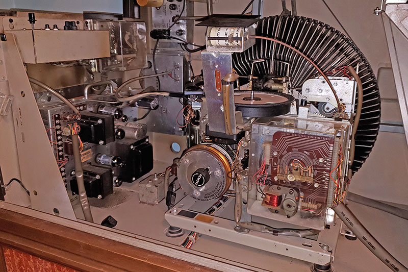


 is closest to the latch solenoid on the left, the select pulse latch relay (R1) is the one closest to the wiring loom on the right.")