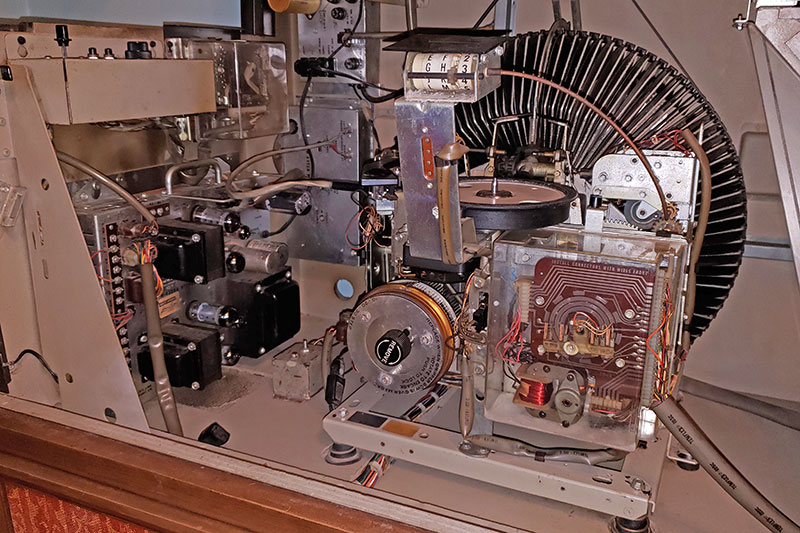
The service manual for the 1971 AMI/Rowe MM5 Presidential jukebox contains lots of useful information. I have trouble with the "Sequence of Operation" pages. They are very nicely described, but I have problems identifying the parts they reference. You really do need the service manual, but this table was written to help me remember where the parts are.
| Operation |
Sequence |
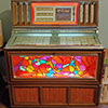
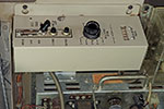
|
| Standby |
Phonograph plugged into power receptacle. |
| Mechanism service switch set to ON position. |
| Cabinet lamps lit. The four fluorescent lights are lit whenever the jukebox is plugged in. |
| Amplifier mute relay energized by 30 V. D. C. The mute relay keeps amplifier quiet during record transfer cycle. |
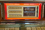
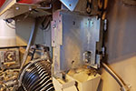
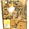
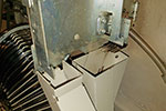
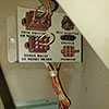
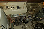
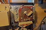
The slug rejector, if one was ever fitted, was removed from this machine some time in the early 1980s. Slug rejectors were fairly standard and those made by National Rejectors Inc. or Coin Acceptors Inc. (aka CoinCo) could be fitted to the plate. I think that when the slug rejector was removed, the wiring from the bonus relay socket to the credit unit was disconnected and replaced with a jumper wire to provide permanent free play. |
| Customer Inserts Quarter |
Quarter passes through slug rejector. |
| Quarter operates 25¢ coin switch lever closing 25¢ coin switch. |
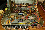
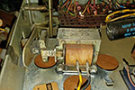
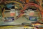
| The coin switch applies 30 V. D. C. to credit coil and credit stop coil in credit unit through pricing switch. |
| Credit coil and adjustable credit stop coil advance credit wiper arm two steps on commutator board corresponding to a quarter. |
|
| Credit Established |
Wiper assembly completes a circuit from the 25¢ two-step credit ring to the 30 V. D.C. ring to energize select pulse latch relay R1 through the letter pushbutton banks. |
| Premium price lamp connected to credit unit commutator board common ring; lamp lights. |
| Circuit completed through latch relay, contacts 7 and 8, to energize latch coil. Pushbuttons will latch into position when pressed. |
| If a letter button is depressed in each of the two letter switch banks, relay R1 and the latch coil will fall out unlatching all letter buttons. This is to insure that two letter buttons in the separate letter switch banks cannot be accidentally latched at the same time. |
| Customer Makes First Selection |
Customer pushes letter pushbutton V and number pushbutton 8. |
| Letter pushbutton switch V completes a circuit to search unit commutator segment UV (rear side of board). |
| Number pushbutton switch 8 completes a circuit to search unit commutator segment 8 (front side of board). |
| Letter pushbutton switch V also opens the circuit to outside row select coil and closes the circuit to inside row select coil. |
| Letter pushbutton switch V and number pushbutton switch 8 complete a circuit to energize start relay R5. |
| Circuit to relay R1 is maintained through letter bank A-K. |
| Search Wipers Locate Number |
When the number search unit wiper (front of commutator board) runs onto segment 8, a circuit is completed to energize sprag relay Sl. |
| The sprag tooth on relay SI stops rotation of search wipers and select coils. |
| Relay Sl, contacts I and 2, complete a circuit to energize search unit relay R2. |
| Search Continues |
Search unit relay R2, contacts 7 and 11, transfer the common side of the circuit from sprag relay Sl to sprag relay S2. |
| Search unit relay R2 holds itself in through contacts 8 and 12. |
| Search unit relay R2, contacts 5 and 9, transfer the positive side of the selection circuit from the number pushbutton switches to the letter pushbutton switches. |
| Sprag relay S1 drops out, contacts 3 and 4 energize search unit motor. |
| When the letter wiper runs onto the UV segment on the rear of the commutator board, sprag relay S2 is energized. |
| Selection Registered, Credit Removed, and Scan Control Operated |
Sprag relay S2 locks the search wipers and select coils in place with the select coils aligned with pins representing selections U8 and V8. |
| Sprag relay S2, contacts 1 and 2, deenergize search unit motor. |
| Sprag relay S2 holds itself in through contacts 6 and 7. |
| Sprag relay S2, contacts 3 and 4, deenergize select pulse and latch relay RI. |
| Select pulse and latch relay RI, contacts 1 and 2, complete a circuit to common to energize scan coil, credit cancel coil and credit cancel stop coil in credit unit, inside row select coil, and total play counter. |
| Inside row select coil pushes pin into select position on the credit unit pinwheel assembly. |
| Credit cancel coil drives the credit wiper arm counterclockwise one step leaving credit for one standard selection. |
| Select pulse and latch relay R1 is held closed for a short time after being deenergized due to a diode connected across the coil. This time delay determines the length of the select pulse to the scan coil, credit cancel coil in the credit unit, and inside row select coil. During this time, search unit relay R2 and start relay R5 are held closed through the letter wiper and pushbutton circuit. |
| Pushbuttons Unlatch and Record Changer Starts |
The time delay across select pulse and latch relay R1 runs out and the relay contacts transfer. This ends the select pulse. |
| The latch coil is deenergized |
| The latch coil plunger releases pushbuttons V and 8. |
| The circuit is opened to search unit relay R2, sprag relay S2, and start relay R5. The relays drop out ending the selection cycle. |
| The customer can now make one more standard price selection. See next sequence, Customer Makes Second Selection. |
| When the scan coil was energized, it tripped the scan control gear closed scan switch. |
| The scan switch energizes the magazine detent coil through mechanism control relay R, contacts 1 and 9. |
| The amplifier mute relay remains energized through cam switch CS-5. |
| Customer Makes Second Selection |
After credit is removed for the first selection, the credit wiper moves counterclockwise to the first step. |
| Wiper assembly completes circuit from one-step standard selection credit ring to 30 V D.C. ring to energize select pulse latch relay RI. |
| Standard price lamp connected to credit unit commutator board common ring; lamp lights. |
| Circuit completed through latch relay, contacts 7 and 8, to energize latch coil. Pushbuttons will latch into position when pressed. |
| Record Magazine Rotates |
Magazine detent coil unlocks the magazine and trips magazine detent switch. |
| The magazine motor rotates the record magazine. |
| Stop Switch Pawl Hits Selected Pin - Transfer Motor Starts |
Inside row stop pawl hits selected pins (V-8). |
| Stop switch operates. |
| Stop switch completes a circuit to energize mechanism control relay R and hub shift coil. |
| Mechanism control relay R, contacts 1 and 9, open deenergizing magazine detent coil. |
| The magazine detent coil releases a linkage that locks the record magazine in position with record UV-8 aligned with the transfer arm. |
| Magazine detent coil linkage also operates magazine detent switch. |
| The magazine detent switch opens the circuit to the magazine motor. |
| Mechanism control relay R, contacts 6 and 10, 11 and 7, energize transfer motor. |
| The hub shift coil raises the turntable 45 rpm hub. |
| If the selection had been a left side or outside row selection, the toggle shift coil would be energized through the left side switch and relay R contacts 5 and 9 |
| Record Picked Up |
The transfer motor drives the transfer assembly and the cam that operates the cam switches. |
| As the transfer assembly begins to move, the cam closes cam switch CS-1 applying power to the turntable motor. |
| Cam switch CS-2 transfers to hold in hub shift coil and mechanism control relay R. |
| The transfer arm picks the record out of the magazine. |
| Record Approaches Turntable |
As the transfer motor to operate, cam switch CS-3 closes. |
| Cam switch CS-3 operates right side annunciator coil and right side reset coil. |
| Right side reset coil plunger resets pin V—8 in the search unit pinwheel assembly. |
| A short time later, cam switch CS-3 opens and cam switch CS-4 transfers to the position opposite that shown. |
| At this time, if selection had been left hand, the toggle shift coil would be deenergized and the left side reset and annunciator coils would be operated by cam switch CS-4. |
| Record Placed On Turntable |
When the selected pin is reset by the reset coil, the stop switch returns to normal position deenergizing reset coil and right side annunciator coil. |
| Assuming that selection V-8 is a 33-rpm, 7-inch LP record, the center of the record strikes the hub switch sensing wire as the record is placed on the turntable. If V-8 was a 45-rpm record, the hub switch sensing wire would not be operated. |
| The hub switch sensing wire actuates the hub switch which deenergizes the hub shift coil and energizes the speed shift coil. This drops the large 45-rpm hub and changes turntable speed to 33-1/3 rpm. |
| When the transfer assembly operates far enough to release the record, cam switch CS-5 operates deenergizing mechanism control relay R and the amplifier mute relay. |
| Mechanism control relay R, contacts 6 and 10, 7 and 11, deenergize the transfer motor by disconnecting it from the common line. |
| The transfer linkage stops moving and the record plays. |
| Record Ends |
When the magnet on the underside of the tone arm operates the tone arm cutoff switch, as the tone arm tracks into the cutoff groove, the amplifier mute relay and mechanism control relay R are energized. The parallel capacitor and series resistor in the mechanism control relay circuit is to delay the pickup of the mechanism. |
| Mechanism control relay contacts 6 and 10, 7 and 11, complete a circuit to common to energize the transfer motor. |
| Record Replaced In Magazine, Magazine Scans |
As the transfer arm places the record in the magazine, the cam operates cam switches CS-1 and CS-2. |
| Cam switchCS-1 deenergizes the turntable motor. |
| Cam switch CS-2 deenergizes mechanism control relay R and the hub shift coil and operates the detent switch. |
| The magazine motor operates until the scan control switch or stop switch operates. |

|
| Premium Price Credit and Selection |
Assume that selections 8A through 8V are all premium price. This is done by moving premium slide #8 to premium price position. |
| When the customer inserts a quarter, twenty-five cents credit is established as in sequence Customer Inserts Quarter and Credit Established. |
| The positive line is connected at number pushbutton switch 1 direct to select pulse and latch relay R1. |
| Selection occurs as in sequences Customer Makes First Selection, Search Wipers Locate Number, Search Continues and Selection Registered, Credit Removed, and Scan Control Operated. |
| Credit removal bypasses cancel stop coil through premium price slide switch #8 and pushbutton switch 8, and two credits are removed. |
| The credit wipers are returned to zero credit position when sprag relay S2 is energized. |
